Printing and Previewing Reports
Mechanic's MateTM is a Maintenance Management System designed to meet the operational and work management needs of today’s modern process, chemical and power plants.
Mechanic's Mate is designed to support the maintenance work order process from the filing of the work order request through the posting of the completed work order. A differentiation between preventive work orders and corrective work orders enables you to schedule tasks effectively and efficiently. Comprehensive system functionality includes parts management, equipment profiles, purchase order generation for parts, employee profiles, and resource management. Safety features include a corrective work order type of “Safety” that is automatically assigned top priority and an area for both corrective and preventive work orders to identify specific safety equipment and procedures.
An intuitive and easy to use system, Mechanic's Mate can be accessed by any employee that has been registered as a user by the system supervisor.
Mechanic's Mate integrates several aspects of plant management to provide a system that completely and effectively manages work order requests and related components.
While the main focus of the system remains on managing work orders, well-developed functionality for the management of equipment, parts and employees is also provided.
The work order functionality provides separate processes for preventive and corrective work orders, enabling you to schedule each in an appropriate and effective manner. Preventive work orders are created by connecting a maintenance task with a piece of equipment and establishing the frequency at which the task should be performed. Corrective work orders are created upon request. Both types of work orders include an area to define safety equipment and procedures.
Equipment management functionality enables you to effectively manage and assess each piece of equipment. The Equipment Profile report gives a full account of when and how the equipment was maintained with detailed and summary costs for parts and labor including the names of the mechanics performing the work.
Personnel management maintains complete records on each plant employee including their position, the training courses they need to complete, the training courses they have completed, and the work orders that they have worked on. The Resource Requirements function enables you to assess the number of employees needed to complete the logged work orders.
Parts management provides base level information for all aspects of the Mechanic's Mate System. Work order functions identify the parts used to complete the task and automatically decrement on-hand stock levels. When a part’s minimum quantity is reached, a purchase order can be automatically generated to restock to the maximum quantity level. Vendor cost information is used to calculate the cost of work orders and ultimately, equipment maintenance at the equipment level.
Purchase order functions enable you to quickly and efficiently assess your parts needs and process the appropriate orders. Using a combination of automatic and manual purchase orders, you can maintain the optimum stock levels for each part.
This User’s Guide is organized by subject area. Within each subject area, system functions are presented and detailed steps for performing specific tasks are provided. Steps for printing reports are included with function documentation. Sample reports and descriptions are presented in Chapter 8.
Basic information about Mechanic's Mate installation and usage is provided in Chapter 1. This includes detailed information about basic system components like screen layout and data entry conventions. Chapters 2 through 8 are written with the assumption that the reader has a working knowledge of Microsoft Windows and has completely read and understood Chapter 1.
To make this document as easy to understand as possible, components of the system are clearly described with the title capitalized and a descriptive term following the title (for example, the Main Menu, the Employee function, etc.). Documentation conventions are covered at the beginning of this User’s Guide.
This section identifies the minimum system configuration needed to install the Mechanic's Mate System and explains how to sign on to the Mechanic's Mate System. Installation instructions are provided in a separate CTI document.
IMPORTANT NOTE: Our third-party report writer, MECHMate REPORT / Stonefield Query, is not covered by this help file. MECHMate REPORT provides its’ own internal Stonefield Query help file.
Your computer workstation should meet the following minimum standards before you install Mechanic's Mate:
Pentium 4 or faster CPU
4 Gigabytes of RAM
Resident hard drive with at least 10 Gigabytes of available space
Microsoft Windows 7 or higher
When your workstation meets these minimum hardware and software requirements, you are ready to begin. Be sure to completely read the installation instructions provided with your system before beginning the installation process.
Each system user has a unique User ID code and Password code. The combination of these two codes identifies them as an authorized user of the system. To ensure continued system security, users should change their passwords periodically.
Users have the ability to access their personal password and update it as necessary. Only the system supervisor can access other users’ passwords and determine each user’s system privileges.
To access the Mechanic's Mate System, users must complete the sign-on process. To ensure system security, users should always exit the system before leaving the workstation. Not exiting the system is like leaving the keys in your car while you go grocery shopping.
After you install the system for the first time, the system supervisor must enter User Setup information for users (see Chapter 7) before anyone else can use the system.
To gain access to the Mechanic's Mate System, you must complete the sign-on procedure. It is a good security policy to require each user to sign-on with their own personal codes, even if they are sharing the same workstation. To transition quickly and easily from one user to another, use the Login Again function on the Utilities menu.
The following procedure explains how to access the Mechanic's Mate System and complete the sign-on procedure:
Double click on the Mechanic's Mate icon in the Windows menu. The system displays the following dialog:
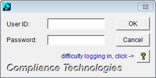
Enter your User ID code in the Log in as field and press the key.
Enter your personal password and press the <Enter> key or press the OK button.
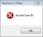
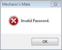
If you enter an incorrect User ID or Password, the system will display a message as shown below:
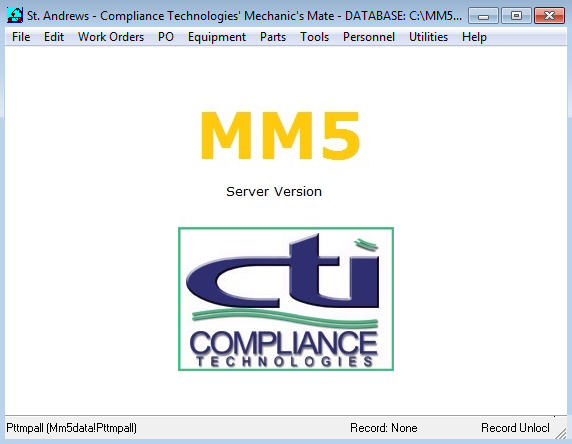
Upon successful Login/Sign On, the Mechanic’s Mate Desktop will be displayed as shown below:
IMPORTANT NOTE: An accurate date and time are important for the effective use of the Mechanic's Mate System. Work orders and course training are closely tied to specific dates. Always check your System Date and Time as displayed in the Windows Taskbar. If the date and/or time are incorrect, access the Date/Time option on the Windows Control Panel and enter the correct date and time.
The Login Again function enables you to quickly access the sign-on screen after another user has already accessed the Mechanic's Mate System. When you complete the Login Again function, the previous user is automatically signed off.
The following procedure explains how to complete the Login Again process:
Access the Login Again function by selecting Utilities from the Main Menu and then selecting Switch User. The system displays the sign-on screen.
Complete the sign-on process as described in the previous section.
The new user is now signed on to the Mechanic's Mate System and the old user has been signed off.
It is very important to exit the system each time you are finished, especially if you are leaving the workstation. There are two methods for signing off, or exiting, the Mechanic's Mate System:
Select File from the Main Menu.
Then select Exit. The Mechanic's Mate screen disappears.
This section provides information about the Mechanic's Mate System that is common to most screens and functions. It is assumed that you have a working knowledge of Microsoft Windows. Basic Windows concepts are not explained. If you are not familiar with Microsoft Windows, you will also want to review their User’s Guide before using the Mechanic's Mate System.
Menus are a basic component of most PC-based systems. They provide easy, organized access to system functions. They help guide you quickly and easily to the function that enables you to perform the desired task.
Like a restaraunt menu, a system menu displays your options and enables you to select the desired item. Effective menus have multiple levels. The first level (known as the Main Menu) offers general categories of system functions. Subsequent levels become more and more specific until all system functions have been offered.
Most system screens display a menu bar across the top of the screen. Although the menu bar can be different for every screen, most Mechanic's Mate screens display the Main Menu (see the following example):
![]()
The Main Menu is the first menu to appear after you access the system. It displays the most general level of menu selections. Most options on a Main Menu lead to a secondary menu that offers a more detailed level of functions.
If a menu option is not available, it appears dimmed or does not display at all. Your system privileges determine which functions are available to you. Contact your system supervisor if you do not have access to a function that you need.
To select an option from a menu, you can:
Click with your mouse on the desired selection, or
Although each Mechanic's Mate screen is unique, the screens contain many common elements. The following Employee screen exhibits many of the common elements:
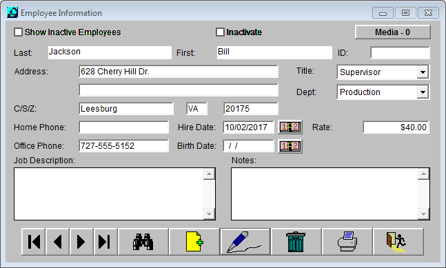
Notice the 3-dimensional beveled look of the screen. Some areas appear raised while others appear submerged. This helps set one subject area apart from another. The User’s Guide documentation sometimes refers to these areas as “boxes”.
The Title Bar displays the name of the dialog. The Dialog Name displays the name of the current screen.
The Text Box is an area of the screen where you can enter or view text. If the entered text exceeds the display area on the screen, scroll bars assist in navigating through the text. Text boxes with a gray background are read-only. Text boxes with a white background can be accessed and edited.
Scroll bars are most often displayed along the right edge of the display window but can also appear along the bottom edge. The icon at the top of the scroll bar moves the display window up so that you can view the next line of text. The icon at the bottom moves the display window down so that you can view the previous line of text. You can also position your cursor on the button in the scroll bar between the icons and drag it up and down in the desired direction for a faster scrolling action.
The Drop Down appears next to fields that enable you to select your entry from an existing list of options. When you click on the icon, the list is displayed and you simply point and click to select your entry.
There are two different kinds of drop-down icons. A small arrow requires that you select your entry from the displayed list. A stockier, bolder arrow allows you to type in your entry and add new entries to the list.
The Datebook Icon appears next to fields that require you to enter a date. When you click on the icon, the system displays dates in a calendar format. You manipulate the calendar to display the appropriate month and year and then click on the desired date.
A Radio Button is a small round circle that precedes each item in a list of options (see following example):
![]()
You click on the radio button preceding the option you want to select. The system darkens the circle to indicate your selection. Radio buttons are usually used when only one option can be selected.
A Toggle Box is a small square box that precedes each item in a set of available options (see following example). Toggle boxes are often used when more than one option can be selected.
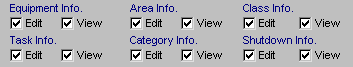
You click on the box of the option you want to select. The system displays an X or mark in the box. To deselect an option, click on the mark. The system will erase it.
The Control Bar contains the navigation buttons and system options for the function. It appears across the bottom of each Mechanic's Mate screen.
The options on the Control Bar vary by function, and change according to the task you are completing. For example, Save and Cancel appear when you are adding or revising a data record. When an option is not available, the system dims it so that only a shadow of the button is visible.
The standard Control Bar contains the following pushbuttons:
|
This navigation button takes you to the first record in a file. |
|
This navigation button takes you to the last record in a file. |
|
This navigation button takes you to the previous record in a file. |
|
This navigation button takes you to the next record in a file. |
|
This button displays a list of the records in the file - also known as a Browse screen. Double click on a record to select it. (See Using Find later in this section for detailed usage information.) |
|
This button initiates the add process used to add new records to the file. |
|
This button gives you access to data in an existing record and enables you to revise the stored information. |
|
This button initiates the delete process used to permanently remove a record from a file. The record displayed on the screen when you press this button is deleted when you complete all steps of the delete process. |
|
This button initiates the print and/or print preview process. See Previewing and Printing Reports later in this section. |
Most Mechanic's Mate screens are easy to understand and use. This section provides detailed information on your data entry options for certain types of fields.
Free form fields and text boxes are areas where you can type in the appropriate information with few restrictions on format or content. You do not have to select from a predefined list and you can enter any combination of letters and numbers.
To enter a free form field or text box, to the field or place the cursor in the field and click the left mouse button. The text area has a white background when you can enter/edit information. The background is shaded when text can only be viewed.
Once you have entered the text area with a white background, begin entering your information. The system will display the characters you enter as they are typed until you have entered the maximum number of characters allowed.
Date fields have specific format restrictions and also offer several methods for entering the date information.
The Mechanic's Mate System uses the MMDDYYYY format for dates where M=month, D=day, and Y=year. The system provides the slash marks that separate each component of the date. If you enter a one-digit month (for example, 1 for January) or a one-digit day, you must also press the right arrow key to move past the slash mark.
The system offers a datebook icon next to each date field that enables you to quickly and easily select your date from a displayed calendar. After you click on the datebook icon, the system displays a window similar to the following:
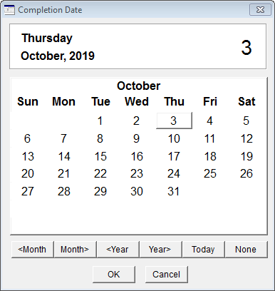
Click on the Month and Year pushbuttons until the desired month is displayed. Then click on the appropriate date. The system inserts the selected date into the field and closes the calendar window.
Many Mechanic's Mate functions contain fields that are linked to a file of data that is created using a different function. For example, the Purchase Order function uses parts that were added to the system using the Part Information function.
These fields come in different flavors. Some are pushbuttons that you press and have the field name on the pushbutton. Some have drop-down icons at the end of the field that you press. Some look like text boxes.
While all of these fields enable you to display a list of existing entries and select your entry, some also enable you to add new entries to the linked file while remaining in the current function and field.
There are two different kinds of drop-down icons. A small arrow requires that you select your entry from the displayed list. A stockier, bolder arrow allows you to type in your entry and add new entries to the list.
Whenever possible, select the item from the list. This helps ensure that your files don’t contain inappropriate or confusing entries. For example, if you type in the entry and it is slightly different from the existing entry, the system adds your new version to the list.
If the field is selected by pressing a pushbutton, the system automatically displays a list of the existing entries. You must select from the displayed list. To add an item to the list, you must access the appropriate function for the specific list that is displayed. For example, the Vendor fields on the Part Information screen require that you select from the defined list of available vendors. To add a new Vendor, you must access the Vendor Information function.
Also see Using the Find Feature, in the following section.
The Find feature located on the Control Bar at the bottom of the screens you select enables you to quickly and efficiently locate a record. After you select Find, the system displays a list of the records in the file.
For example, select Personnel /Training from the main menu, then press Find.
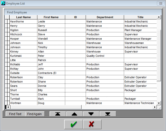
If the record you want is already displayed, just double click on it to select it. Otherwise, you have several options for displaying an individual record from the list:
Use the scroll bar to scroll through the list.
Begin entering the first characters of the key information for the file. For example, start entering the last name of an employee if you are in the Employee file. The Key box in the top right corner of the screen displays the keystrokes it is recording. The system then takes you to the nearest record that starts with the characters you have entered.
Use the up and down directional arrows on your keyboard to navigate through the list.
The Find feature provides great flexibility, enabling you to temporarily rearrange the list to display information in a manner that best supports your needs. Your changes remain effective as long as the window is open. Your changes do not affect the database file, only how the information is displayed in the current window.
You can make the columns thinner or wider. Position the cursor in the column headings and place on the column border that you want to move. When the double headed arrow symbol appears, click and drag the column border to the desired width. The columns to the right of the new border will automatically adjust to the newly defined available space.
You can change the sequence of the columns. For example, you might prefer to have SSN in the first column instead of Last Name. Although you can change the order of the columns, you cannot change the sort sequence of the listed records (for example, the Employee List always presents employees in alphanumeric sequence using the employee’s last name regardless of the sequence of columns).
Position your cursor in the heading of the column you want to move. Click and drag the mouse until the column appears in the desired location. Release the mouse and the newly arranged list will display.
Splitting the window enables you to view two different areas of the list simultaneously. This feature is especially useful for records with a long row size. Once split, each partition of the window has a separate horizontal scroll bar. This enables you to view columns 1 and 2 in the left partition and columns 6 and 7 in the right partition. The vertical scroll bar is shared by both partitions.
To split the window, move your cursor to the dark area in the bottom left corner of the window. When the double-headed arrow symbol appears, click and drag to the right until both partitions are the desired size. To return to a single partition, reverse the above steps.
The system displays an Invalid Input Log when you attempt to save a screen before completing all fields of required information. The Invalid Input Log contains a list of the information that you need to provide in order to save the screen (see following example):
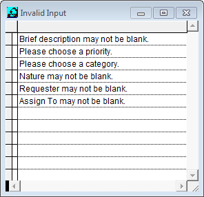
This example was generated by attempting to save a CM work order without entering any information.
When you press or , the system returns to the function screen so you can input the necessary information.
The Invalid Input Log will continue to display each time you press Save until all required information has been entered.
The Mechanic's Mate System contains more than 40 different lists and reports that can be previewed on-line or printed to a printer. While the screens displayed during the preview/print process might be slightly different for each report, the general process is the same for all reports and lists.
Sample reports and report descriptions are provided in Chapter 8 Reports. Detailed instructions for printing reports are provided with the description of the function used to generate the list or report. For example, the Part Information section contains the instructions for generating the Parts List.
The Mechanic's Mate System uses your Windows print drivers and utilizes the Windows print screens. See individual printing instructions for an example. Consult your Windows manual for detailed information about using the Windows print screen and drivers.
Each report or list offers the option to preview the report on-line. It is often useful to view the report on-line before sending it to the printer. For example, you may only need to print a subset of the report’s pages. The preview feature enables you to identify the page numbers that you need.
The preview feature is strictly a viewing option and does not offer any editing capabilities.
Use the following procedures to preview a report or list:
Access the function that generates the report or list.
Press the Print/`Preview
![]() button on the Control Bar.
button on the Control Bar.
The system displays a screen that displays your reporting options including three pushbuttons near the bottom of the screen. The pushbuttons provide the ability to Preview, Print, or Cancel.
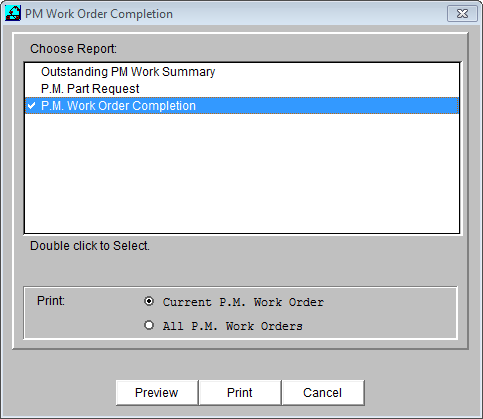
Set your report options as you want them and then press Preview. The system displays a screen similar to the following:
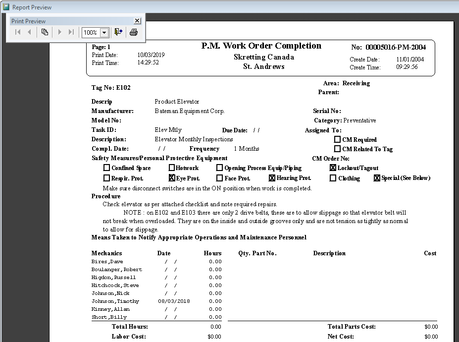
The system displays the report as it will appear when it prints from the printer. Your viewing pushbuttons are provided at the right side of the window for easy access.
The Next and the Previous buttons enable you to page back and forth through the report, one page at a time. The Next button takes you to the next page. The Previous button takes you to the previous page. If you are viewing the last page of the report, the Next button is dimmed because a next page does not exist. If you are viewing the first page of the report, the Previous button is dimmed because a previous page does not exist. If the report consists of a single page, both the Next and the Previous buttons are dimmed.
The page button enables you to immediately access a specific page of the report. The page field identifies the page number that is currently displayed. This feature is especially useful for lengthy reports.
There are two zoom buttons: Zoom In and Zoom Out. When the report is first displayed, the full page appears and the Zoom Out button is dimmed. To take a closer look at the page, press Zoom In (notice that the Zoom In button is now dimmed and Zoom Out is not dimmed). Use the horizontal and vertical scroll bars to examine the specific area of the page that you want to view. To return to a full page display, press Zoom Out.
When you are finished previewing the report, press OK. The system returns you to the report options window.
To print the report, press Print. To exit the report options window without printing a report, press Cancel.
See individual function descriptions for detailed printing instructions.
The following conventions are maintained throughout this manual in order to emphasize menu selections, user-interaction, file names, and other standards.
Convention |
Description |
NOTE: |
Precedes information of general importance. |
HINT: |
Precedes optional time-saving information. |
WARNING: |
Precedes information about actions that should not be performed under normal operating conditions. |
FILENAMES |
Directory
paths and file names are italicized. |
Program Code |
Excerpts from text or basic script files, script variables, and statements appear in the font shown. |
INPUT |
Commands or information that must be manually entered is bolded in the font shown. |
Menu
& |
Menu
commands and dialog buttons appear in a sans serif font that
stands out from normal body text. |
|
Individual
keyboard keys, or key combinations, are graphically represented.
|
Dialogs |
Dialog
and database table names are italicized. |
Select |
Indicates that the command must be executed from a menu or dialog. |
Pick |
Indicates an item (component or point) that may be picked on a drawing. |
My name is Thurston Clark, and I am the original and sole programmer of the Mechanic's Mate CMMS. I wrote every line of code, starting in the 1990s with FoxPro 2.6 and migrating it through to its current version in FoxPro 9.
To ensure the continuity of the software, I am available for expert support, data recovery, and custom modifications. You can read the full development case study for Mechanic's Mate on my professional portfolio site to learn more about my background.
If you are a current user needing assistance or a new customer with questions, please do not hesitate to reach out. You will be speaking directly with the programmer who wrote every line of its code.
Ready to take control of your maintenance operations and own your data?
Explore the Mechanic's Mate CMMS Product Page.
For support or inquiries, please Contact Me Here.